The NEC program uses both an electric-field integral equation (EFIE) and a magnetic-field integral equation (MFIE) to model the electromagnetic response of general structures. Each equation has advantages for particular structure types. The EFIE is well suited for thin-wire structures of small or vanishing conductor volume while the MFIE, which fails for the thin-wire case, is more attractive for voluminous structures, especially those having large smooth surfaces. The EFIE can also be used to model surfaces and is preferred for thin structures where there is little separation between a front and back surface. Although the EFIE is specialized to thin wires in this program, it has been used to represent surfaces by wire grids with reasonable success for far-field quantities but with variable accuracy for surface fields. For a structure containing both wires and surfaces the EFIE and HFIE are coupled. This combination of the EFIE and MFIE was proposed and used by Albertsen, Hansen, and Jensen at the Technical University of Denmark (ref. 9) although the details of their numerical solution differ from those in NEC. A rigorous derivation of the EFIE and MFIE used in NEC is given by Poggio dnd Hiller (ref. 10). The equations and their derivation are outlined in the following sections.
1. THE ELECTRIC FIELD INTEGRAL EQUATION (EFTE) The
form of the EFIE used in NEC follows from an integral representation for the
electric field of a volume current distribution
![]() , Equation(1)where Equation(1a)and the time convention is exp(jwt).
, Equation(1)where Equation(1a)and the time convention is exp(jwt).
![]() is the identity dyad
is the identity dyad
![]() . When the current
distribution is limited to the surface of a perfectly conducting body,
equation (1) becomes Equation (2)with
. When the current
distribution is limited to the surface of a perfectly conducting body,
equation (1) becomes Equation (2)with
![]() the surface current
density. The observation point
the surface current
density. The observation point
![]() is restricted to be
off the surface S so that
is restricted to be
off the surface S so that
![]() .
.
If ![]() approaches S
as a limit, equation (2) becomes
Equation (3)Where the principal value integral,
approaches S
as a limit, equation (2) becomes
Equation (3)Where the principal value integral,
![]() , is indicated since
, is indicated since
![]() is now
unbounded.
is now
unbounded.
An integral equation for the current induced on S by an incident field
![]() can be obtained
from equation (3) and the boundary condition for
can be obtained
from equation (3) and the boundary condition for![]()
![]() S,
Equation (4)where
S,
Equation (4)where
![]() is the unit
normal vector of the surface at
is the unit
normal vector of the surface at
![]() and
and
![]() is the field
due to the induced current
is the field
due to the induced current ![]() . Substituting equation (3) for
. Substituting equation (3) for
![]() yields the
integral equation,Equation (5)
yields the
integral equation,Equation (5)
The vector integral in equation (5) can be reduced to a scalar integral equation when the conducting surface S is that of a cylindrical thin wire, thereby making the solution much easier. The assumptions applied for a thin wire, known as the thin-wire approximation, are as follows:
a. Transverse currents can be neglected relative to axial currents on the wire.
b. The circumferential variation in the axial current can be neglected.
c. The current can be represented by a filament on the wire axis.
d. The boundary condition on the electric field need be enforcrd in the axial direction only.
These widely used approximations are valid as long as the wire radius is much less than the wavelength and much less than the wire length. An alternate kernel for the EFIE, based on an extended thin-wire approximation in which condition c is relaxed, is also included in NEC for wires having too large a radius for the thin-wire approximation (ref. 11).
From assumptions a, b and c, the surface current
![]() (
(![]() ) on a wire of radius a
can be replaced by a filamentary current I where
) on a wire of radius a
can be replaced by a filamentary current I where
Equation (5) then becomes
Equation6 where the integration is over the length
of the wire. Enforcing the boundary condition in the axial direction reduces
Eq. (6) to the scalar equation,
Equation(7) Since
![]() ' is now the point at
s' on the wire axis while
' is now the point at
s' on the wire axis while
![]() is a point at s on
the wire surface |
is a point at s on
the wire surface |![]() -
-
![]() '|
'|![]() a and the integrand
is bounded.
a and the integrand
is bounded.
2. THE MAGNETIC FIELD INIEGRAL EQUATION (MFIE) The
MFIE is derived from the integral representation for the magnetic field of a
surface current distribution
![]() . Equation (8) where the differentiation is with respect
to the integration variable
. Equation (8) where the differentiation is with respect
to the integration variable
![]() . If the current
. If the current
![]() is induced by an external
incident field
is induced by an external
incident field ![]() ,
then the total magnetic field inside the perfectly conducting surface must be
zero. Hence, for
,
then the total magnetic field inside the perfectly conducting surface must be
zero. Hence, for ![]() just inside the surface S, Equation(9) where
just inside the surface S, Equation(9) where
![]() is the incident
field with the structure removed, and
is the incident
field with the structure removed, and
![]() is the scattered
field given by equation (8). The integral equation
for
is the scattered
field given by equation (8). The integral equation
for ![]() may be obtained by
letting
may be obtained by
letting ![]() approach the
surface point
approach the
surface point ![]() from
inside the surface along the normal
from
inside the surface along the normal
![]() · The surface
component of equation (9) with
equation (8) substituted for
· The surface
component of equation (9) with
equation (8) substituted for
![]() is then
Equation (9a) where
is then
Equation (9a) where
![]() is the outward
directed normal vector at
is the outward
directed normal vector at
![]() . The Limit can be
evaluated by using a result of potential theory (ref. 12) to yield the integral equation
Equation (10) For solution in NEC, this vector
integral equation is resolved into two scalar equations along the orthogonal
surface vectors
. The Limit can be
evaluated by using a result of potential theory (ref. 12) to yield the integral equation
Equation (10) For solution in NEC, this vector
integral equation is resolved into two scalar equations along the orthogonal
surface vectors
![]() and
and
![]() where
Equation (10a) By using the identity
where
Equation (10a) By using the identity
![]() and noting that
and noting that
![]() and
and![]() , the scalar
equation can be written, Equation (11)
Equation (12) These two components suffice since
there is no normal component of equation (10).
, the scalar
equation can be written, Equation (11)
Equation (12) These two components suffice since
there is no normal component of equation (10).
3. THE EFIE-MFIE HYBRID EQUATION Program NEC
uses the EFIE for thin wires and the MFIE for surfaces. For a structure
consisting of both wires and surfaces,
![]() in
equation (7) is restricted to the wires, with the
integral for
in
equation (7) is restricted to the wires, with the
integral for ![]() ,
extending over the complete structure. The thin-wire form of the integral in
equation (7) is used over wires while the more
general form of equation (5) must be used on
surfaces. Likewise,
,
extending over the complete structure. The thin-wire form of the integral in
equation (7) is used over wires while the more
general form of equation (5) must be used on
surfaces. Likewise, ![]() is restricted to surfaces in equations (11) and
(12), with the integrals for
is restricted to surfaces in equations (11) and
(12), with the integrals for
![]() extending over
the complete structue. On wires the integral is simplified by the thin-wire
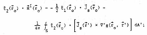
approximation. The resulting coupled integral equations are, for
extending over
the complete structue. On wires the integral is simplified by the thin-wire
approximation. The resulting coupled integral equations are, for
![]() on wire surfaces,
Equation (13) and for
on wire surfaces,
Equation (13) and for
![]() on survaces
excludeing wires Equation (13a) and Equation
(13b) The symble
on survaces
excludeing wires Equation (13a) and Equation
(13b) The symble
![]() represents
integration over wires while
represents
integration over wires while
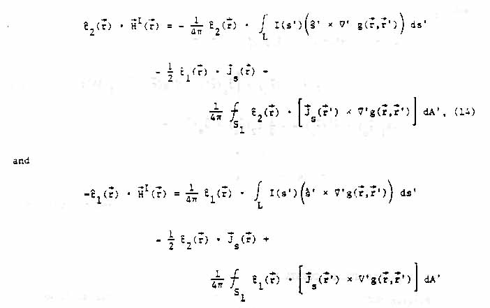
![]() represents intergration over survaces exluding wires. The numerical method used
to solve equations (13), (14) and (15) is
described in section III
represents intergration over survaces exluding wires. The numerical method used
to solve equations (13), (14) and (15) is
described in section III